The first step in performing a calculation is defining the structure. At the highest level, a structure consists of three components: the ambient material, the multilayer stack, and (optionally) a substrate. Although the different structure components are specified in somewhat different ways, as described in section 2.2, common to all structure elements is the material designation, which determines what optical constants are used for the calculation. This section discusses material designation and optical constants.
Each structure element - the ambient, the substrate, and each multilayer stack layer element - is composed of some material. There are two different methods you can use to designate materials:
The use of the two methods for material designation is best illustrated by example. But before illustrating the techniques for material specification, I will describe in the next section the IMD optical constants database.
BROWSING THE IMD OPTICAL CONSTANTS DATABASE
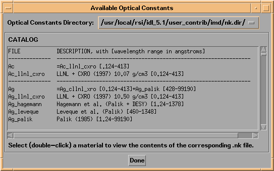
To see which materials are available (and over which wavelengths) in the IMD optical constant database, i.e., the materials available for use by the first method of material specification above, select Materials/Optical Constants -> Browse Optical Constants Database from the menu bar. Doing so will bring up the catalog of available optical constants, as shown in Figure 2.1.1:
Figure 2.1.1 IMD Available Optical Constants widget

Each available optical constant file is listed, along with abbreviated source reference and wavelength coverage information. By selecting an item from the catalog, two new widgets will appear: one displaying a text listing of the optical constants contained in the file you selected, and another (an XNKPLOT widget) showing a plot of the optical constants (n and k) versus wavelength. For example, shown in Figure 2.1.2 are the optical constants for silver:
Figure 2.1.2 XNKPLOT of the optical constants of Ag
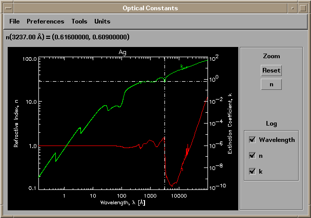
You can use the XNKPLOT Prefences menu items to adjust the appearance of the optical constants plot, and you can print the plot using the File->Print menu option (as if you couldn't have figured that one out.)
Consult Appendix A for more details on optical constants, including how to use your own optical constants, and how to create new X-ray optical constants.
As mentioned above, there are two different methods available for material designation in IMD. These two methods will now be described in more detail. Although the material designation techniques described here apply to all structure elements - ambient, substrate and layers - I will show how to specify the material in a layer element as a specific example.
METHOD 1: Material designation by reference to an optical constants file
Shown in Figure 2.1.3 is the layer widget associated with a new layer. (i.e., the widget that appears when you press the Add Layer button; the techniques for adding a new layer to the multilayer stack are described fully in section 2.2.)
Figure 2.1.3 An IMD Layer widget, as it appears when a new layer is added to the multilayer stack.
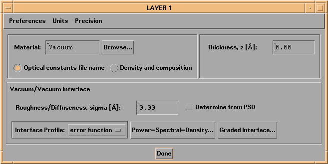
The Optical constants file name button is selected by default, indicating that material designation is by reference to a valid optical constants file. The default layer material is "Vacuum", which means that the optical constants (n,k) have the value of (1.,0.) for all wavelengths. (Indeed, "Vacuum" is the default material for all new structure elements.) To change the material, you can enter a (valid) material name in the material field, or else press the Browse... button to display a choice of all available materials, as show in the next figure (entering an invalid material name has the same effect as pressing the Browse... button):
Figure 2.1.4 Pressing the Browse... button: the IMD material selection widget
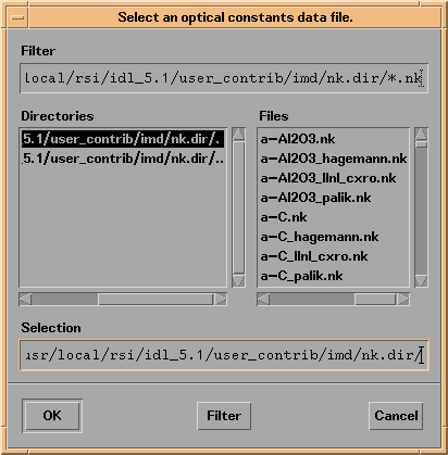
The material selection widget lists all available optical constant files (.nk files). You can scroll through the list of available files and select the material you like by clicking on the file name, and pressing the OK button.
Note: you'll see that there are no files named 'Vacuum' available. To designate Vacuum as a material, you must either type 'Vacuum' in the material field (or leave it blank) and hit return.
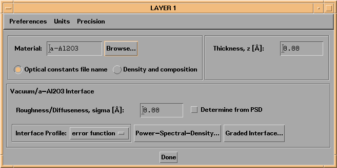
As an example, shown in Figure 2.1.5 is the Layer widget after selecting amorphous aluminum oxide - the first choice in the list of available optical constants show in Figure 2.1.4.
Figure 2.1.5: IMD Layer widget corresponding to an amorphous aluminum oxide layer.
METHOD 2: Material designation by density and composition specification
To utilize the second method for material specification, click on the Density and composition button. Doing so will cause the Layer widget to appear as in Figure 2.1.6.
Figure 2.1.6: An IMD Layer widget with the Density and composition button selected.
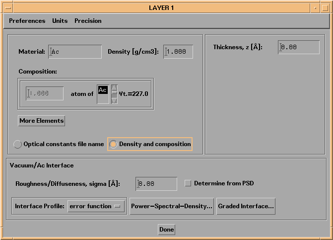
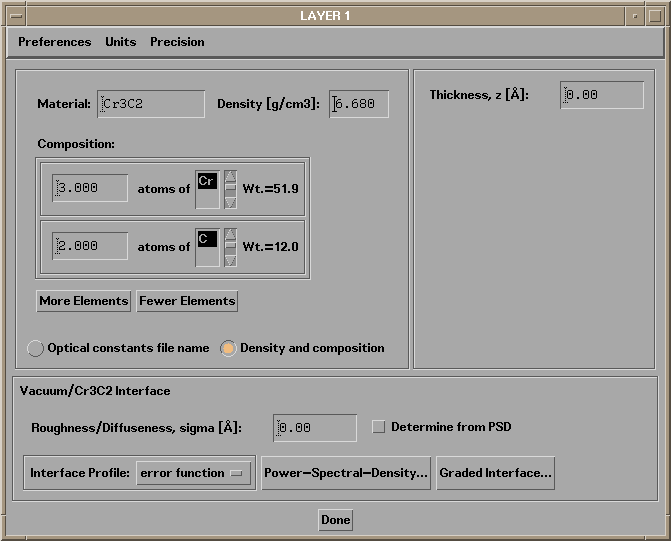
When specifying a material by density and composition, you must specify how many different elements comprise the compound (using the More Elements and Fewer Elements buttons), the names of the elements (by selecting from the list of the 92 available elements,) the relative numbers of each element, and the density (in grams/cm3) of the compound. The Precision menu allows you to adjust the number of decimal spaces displayed for both density and composition values. As an example, shown in Figure 2.1.7 is a Layer widget configured to use a material consisting of 3 parts Cr and 2 parts C, having a density of 6.68 gm/cm3.
Figure 2.1.7: An IMD Layer widget corresponding to a layer of Cr3C2, having a density of 6.68 gm/cm3.
Note: material specification by density and composition is applicable only in the photon energy range from 30 eV to 100 keV (i.e., wavelengths between 413 and 0.124 angstroms.) See Appendix A.3 for more details.
Regardless of which method you use to specify a material, the results of your material selection will be listed in the Structure List. For example, if you have chosen water as the ambient material, the Structure List will indicate 'ambient: H2O'.